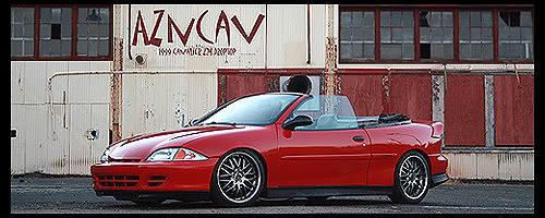
I want to correct this

with this

and the semi fail result

the spacer is not tall enough, but you can see the tie rod end is perfect
Location: Montreal, Quebec
Indeed it is. So youre spacing the ball joint from the CA?

TheSundownFire (GME Chat) wrote:Indeed it is. So youre spacing the ball joint from the CA?
yes and I have bolted the tie rod end from under on the knuckle I will post more soon
Location: Montreal, Quebec
Where is the pivot between the tie rod end and the rack in relation to the subframe? Roughly the same distance from the centerline of the car?
.


Spacing the balljoint like that might change the angle of the arm, but it hasn't changed the relative pivot points, so roll center hasn't changed. The spacer needs to go on the knuckle side of the balljoint, not the arm side...
The tie rod end is interesting. Do you have any clearance issues with wheel extension (jacking the car up)?
 fortune cookie say: better a delay than a disaster
TheSundownFire (GME Chat) wrote:Indeed it is. So youre spacing the ball joint from the CA?
Yes, in doing so he will be correcting the roll center of the suspension. Personally I think it would be more beneficial to make a set of new arms that would be stronger and lighter, and also correct the roll center. The only problem I see with your fix is, #1 it will only be good for one drop. There is play in that style of fixing, but if someone is running CO or springs the spacer will have to be different thicknesses.#2 the pivot angle as someone mentioned will need to be determined so that there is no binding of the knuckle to CA when compressed and so on.
On a side noteI thinking your machining is superb by the way
 http://www.overkillengineeringmotorsports.com/
James Cahill wrote:Where is the pivot between the tie rod end and the rack in relation to the subframe? Roughly the same distance from the centerline of the car?
.
maybe a bite lower with the stock rod end
OHV notec wrote:Spacing the balljoint like that might change the angle of the arm, but it hasn't changed the relative pivot points, so roll center hasn't changed. The spacer needs to go on the knuckle side of the balljoint, not the arm side...
The tie rod end is interesting. Do you have any clearance issues with wheel extension (jacking the car up)?
I know the pivot point dont change, but most of the kit that i see on the web are build like that
I have 19" wheels so I have a lot of clearance

OEM wrote:TheSundownFire (GME Chat) wrote:Indeed it is. So youre spacing the ball joint from the CA?
The only problem I see with your fix is, #1 it will only be good for one drop. There is play in that style of fixing, but if someone is running CO or springs the spacer will have to be different thicknesses
On a side noteI thinking your machining is superb by the way 
This is not a problem it's only for my car

And thank you

Location: Montreal, Quebec
Looks good, was contemplating on boring and sleeving the tie rod to flip it.
"Oil Leak ? What oil Leak ? Oh, Thats Just The Sweat From All The HorsePower!!"
ok so help me get what i am seeing here... this thread reached the limits of my suspension understanding, unfortunately.

you've lowered the car so much that the CA is no longer at the ideal location of parallel to the ground.. right? so to correct that you made a bushing that pushed it back to where the CA was a bit closer... better for handling. i get that part.
but i dont really get moving the tie rod part... same principal im assuming? that the car is so lowered that now the the tie rod is in the wrong position?
 Oldsmobile all motor > Saab/Opel boosted
i need those knuckles for my ssbc brakes ! lol interesting post though.

OEM wrote:
http://www.sr20-forum.com/bolt-bars/30241-bumpsteer-kit.html
This was my first idea but I chose a fancy way

z yaaaa wrote:but i dont really get moving the tie rod part... same principal im assuming? that the car is so lowered that now the the tie rod is in the wrong position?
This video will explain way better then me
Location: Montreal, Quebec
is that the nbody knuckle? i wish it worked with jbody hubs


Interested to see what a bump-steer gauge has to say.
Is that the stock stud on the tie-rod?
Would it not be more beneficial to go with a heim-joint setup, with a longer stud and spacers so you can space the tie rod further from the spindle? (ex. the tie rod will bind if any lower, etc.)
Theres no doubt that what you have done will change the bump-steer 100%, but am just curious if you had taken other things into consideration.
Awesome work! Go get an alignment!!!

Im interested in the ball joint spacers, my CA bushings hate me when i ride so low and lay out.
I got the car aligned today and now the car is @!#$ dangerous lol
any small bump on the road make the car dance
back to the drawing board
Location: Montreal, Quebec
OEM wrote:What are the specs on your alignment? What did they put your TOE to?
near to zero degree
the guy sat in the car and the toe change to like .5 degree
Location: Montreal, Quebec
That vid helped me understand more
~2014 New Z under the knife, same heart different body~
______________________
WHITECAVY no more
2012 numbers - 4SPD AUTOMATIC!!
328 HP
306 TQ
I make this nice bump steer gauge today
I will try to adjust the bump steer the right way this time


Location: Montreal, Quebec
Heyy you forgot the level thingie lol
~2014 New Z under the knife, same heart different body~
______________________
WHITECAVY no more
2012 numbers - 4SPD AUTOMATIC!!
328 HP
306 TQ


