Cam Position Sensor, What does it read and when. - Tuning Forum
Forum Post / Reply
You must log in before you can post or reply to messages.
I'm wondering if there would be any interest in a inline electronic box that will allow you guys to run COP with a aftermarket ECU. What I've got right now is a switching box the has two wire input from the coil trigger wires, a 3 wire(1wire input into the switching box, other 2 wires, +12 and GND) hall sensor with a flying magnet on the cam pulley lined up with Cyl #1 TDC-PS which gives the switching box the ability to know when to set which trigger wire to exactly which cylinder. So the switching box has 2 spark channel inputs with 4 spark channel outputs, and knows which cyl. fires next by knowing where Cyl#1 PS is and then following the firing order. I'm running this in tandem with my DIS II which is fine but will only allow 7krpm is full COP since it runs 14k in DIS, I still have the stock limit so I haven't verified this but it works great up to stock limiter. Anyway, it was alot of work and I was bored. Anyway, if anybody knows how the CPS reads I'd be interested. I should be able to use the factory CPS, which would simplify this alot.
Hopefully it should be simple, like setup resistors to switch triggers 1(1,3) & 2(2,4) to like trigger 1=1 and trigger 2=2 when CPS is in positive state and then switch back when CPS is in negative state leaving the triggers as so: trigger 1=3 and trigger 2=4. Then this box could be put before a DIS4 unit and used to fire the independent coil inputs on the DIS4 and then out to 4 real pencil coils on top of the spark plugs....anybody know anything about the CPS? This is kinda a novelty, but the kinda stuff that interests me.
Did this make since?
"Never argue with an idiot. They'll drag you down to their level, then beat you with experience!" -Anonymous
Sorry, let me fix this:
Joshua Dearman wrote:I'm wondering if there would be any interest in a inline electronic box that will allow you guys to run COP(Coil on Plug) without an aftermarket ECU. What I've got right now is a switching box the has two wire input from the coil trigger wires, a 3 wire(1wire input into the switching box, other 2 wires, +12 and GND) hall sensor with a flying magnet on the cam pulley lined up with Cyl #1 TDC-PS which gives the switching box the ability to know when to set which trigger wire to exactly which cylinder. So the switching box has 2 spark channel inputs with 4 spark channel outputs, and knows which cyl. fires next by knowing where Cyl#1 PS is and then following the firing order. I'm running this in tandem with my DIS II which is fine but will only allow 7krpm is full COP since it runs 14k in DIS, I still have the stock limit so I haven't verified this but it works great up to stock limiter. Anyway, it was alot of work and I was bored. Anyway, if anybody knows how the CPS reads I'd be interested. I should be able to use the factory CPS, which would simplify this alot.
Hopefully it should be simple, like setup transistors to switch triggers 1(1,3) & 2(2,4) to like trigger 1=1 and trigger 2=2 when CPS is in positive state and then switch back when CPS is in negative state leaving the triggers as so: trigger 1=3 and trigger 2=4. Then this box could be put before a DIS4 unit and used to fire the independent coil inputs on the DIS4 and then out to 4 real pencil coils on top of the spark plugs....anybody know anything about the CPS? This is kinda a novelty, but the kinda stuff that interests me.
Did this make since?
You can also use this for CNP if you want to use a cheaper solution like using a V8 DIS coil pack
Edited 1 time(s). Last edited Tuesday, March 10, 2009 2:50 PM
"Never argue with an idiot. They'll drag you down to their level, then beat you with experience!" -Anonymous
Working on that very thing now... just have to get past the wast spark thing...
Chris
'02 Z-24 Supercharged
13.7 @102.45 MPH Third Place, 2007 GMSC Bash SOLD AS OF 01MAR08
Let me know what you might find on the sensor. It's 3 wires right? If it is it would make it possible to find out which cyl 1or3 is in it's PS when the sensor is either 12/5+ or grounded by just running a wire directly to the battery to power the sensor while hand turning of the crank would be possible.
"Never argue with an idiot. They'll drag you down to their level, then beat you with experience!" -Anonymous
I am curious about the CPS sensors functionality as well... But not for COP... I am trying to setup my ignition (msd dis-2 programmable) for individual cylinder timing control... but i need a CPS in order to do this.... I know our cars already have one... but it is what i believe to be a 3-wire hall sensor running a 12v signal feed.... and my ignition appears to be looking for a flying magnet sensor with a 5v signal.
So just trying to figure out if there is a way to make this work without having to run 2 seperate cam sensors.
If i better understood how the factory CPS/hall works and how that differs from the flying magnet that MSD sells, i could better understand how to rig it up to trigger my ignition.
My general understanding is that both types are just a switch... as the magnet/indicator/etc passes by the sensor, it changes the circuit. either momentarily breaks the signal, or momentarily pulses on. (depending on if the sensor is normally open or normally closed)
but either way... as long as the stock sensor changes states when cyl 1 is a tdc... i should be able to make it work... a simple 5-pin relay spliced into the CPS to open and close a seperate circuit would allow you to convert a 12v N.O signal to a 5v N.C. signal no problem.
just need a better idea of how they both work... with pin-outs and all...
(i am doing this on an LD9 what engine are you both working with for your COP setups?)

^sounds good. but dont use a relay, use a HEXFET transistor...a relay will not give you the pulses fast enough. HEXFETs(depending on the type) can cycle at like 2khz and sink like 5 amps.
"Never argue with an idiot. They'll drag you down to their level, then beat you with experience!" -Anonymous
Ok well here is what i found out about the CPS on the LD9 at least... I would imagine it is the same or similar on other chevy 4cyls...
the pin out for the sensor is
pin1 - Signal - Brown and white wire
pin2 - Ground - black wire (possible pink stripe)
pin3 - 12v - red wire (possible white stripe)
(but on some V6 engines it is different. pin1=12v, Pin2=signal, pin3=ground... so this may be an alternative pinout on some other cavy engines too.)
This is not a normal 5v sensor.. it uses a 12v feed, and returns a binary signal of 10v or 0volts. It is a normally closed circuit. So with no trigger, the sensor should always read 10v on the Brown wire.
Technically our sensor is NOT a flying magnet sensor... simply by the fact the "Trigger" on our cams is in no way magnetic. The magnet is in the sensor itself, and the trigger is merely any form of iron to pass within the sensors magnetic field. In the case of the LD9 at least, the trigger is basically an extra "lobe" on the intake cam. It covers 180* of the camshaft.
I would assume, but have yet to verify, that the signal wire should show 10v for half the engines revolution, and 0v for the other half, with the state change from 10v-0v at TDC of Cylinder 1. (and i would assume from 0v back to 10v would indicate TDC of whatever cylinder was 3rd in firing order)
As soon as i get out to the garage i will verify all this and post up.
here is a good site with alot of info and pics on this topic.
http://www.automotivehelper.com/topic663359.htm
As far as my needs go... i have to figure out a way to translate this into what appears to be a 5v 2 wire "flying magnet" sensor. my MSD box has a 2wire connector for the CPS... None of the MSD manuals or diagrams explain WHAT these are... just how to hook it to THEIR sensor. When i hook a mulitmeter to the leads, i get what appears to be 5v on both wires. I am going to post up on MSD's forums to see if they can explain this. But just wondered if anyone here knew how that works. I would guess that the 2 wires would just be a positive and a ground... and would just be looking to see if the sensor completed the circuit or not.

You could run a RC pull-up transistor circuit that will switch state when the voltage increases or decreases quickly but then saturates very quickly after the change has passed. That will give you what your looking for.
Edited 1 time(s). Last edited Saturday, March 21, 2009 7:51 AM
"Never argue with an idiot. They'll drag you down to their level, then beat you with experience!" -Anonymous
MSD Forums wrote:What the output signal from the HAll Effect needs to be to trigger the MSD ignition is a POSITIVE square wave with a 20° duty cycle at battery amplitude.
Um... so this is a little over my head. I never claimed to be an electrical engineer.

I assume this means that "the cam sensor needs to put out a 12v signal (battery amplitude) that switches off (square wave) for 20* of the rotation of the cam (i assume starting at 0* TDC of cylinder 1 and ending at 20* retard.)
correct me (i know there is no "if" about it) im wrong.
oh... and sorry for stealing your thread... trying to give back something too though.

^So what the MSD is looking for is a square wave like: ________|-----|________ where the square wave up top is only 20 degrees of the cam. So, without a saturated RC circuit pushing a pull-up leg on a transistor your not gonna get it to work. So basically what you need to do is build a circuit that when the cam switches from +10 V or GND the transistor activates feeding battery 12V+ thru the transistor leg into the MSD box, then the RC will saturate and pull the resistor shut after 20 degrees, you will have to calculate an RC time and calibrate your capacitor to make this happen. So the input into the transistor will require much less than what your sensor needs to read but as long as it's open it will send +12V from the battery right. So the gate(or collector can't remember which right now) on the transistor will look more like this: ______/****----___ with a falling edge until the transistor finally shuts but when the transistor opens all the way until it closes up you will get a +12V going tru the transistor leg and waveform will look like the square wave up there^
I know thats hard to follow, but your gonna learn ALOT doing a project like this....lol
Good luck.
"Never argue with an idiot. They'll drag you down to their level, then beat you with experience!" -Anonymous
Excellent!!! that is what i love to hear.
For me the knowledge gained in attempting new things is more valuable than the initial purpose of the attempt.
I didnt know squat about fuel injection or engine building before this forum. Let alone forced induction or tuning....
And now i own a cavalier with a fully built 2.4Lthat was completely hand assembled by me, turboed, supercharged, almost fully tuned....
and she can keep right up with a cobalt SS turbo from 50mph on without ever touching 3rd gear (cobalt giving it all she had all starting in 3rd).
and it all started with a few curious posts on a forum....

So yes i love my car. But even more i love the fact that i did it all myself and learned a freaking S**TLOAD doing it.
My car could blow up tomorrow, but my experience and new found knowledge will last forever, and have already saved my ass and helped out many people around me.

I'll think about it more and I can be more help in the near future, this is just a bad week but the more I think about it you will have to run two sets of transistors........thinking.......
I'll come back with a wiring diagram later...thinking.....
"Never argue with an idiot. They'll drag you down to their level, then beat you with experience!" -Anonymous
ok.... what the heck kinda wave is this?
This is me tapping into the signal wire of the CPS on my 2.4L, and entering it as a EIO and logging it.
that is the voltage graph i am getting from my CPS at about 1000rpm...
I am really confused... this doesnt look like a very complex device... a magnet with some metal spinning around... i figured it would be a real simple on off on off on off type thing.... but um... obviously not.
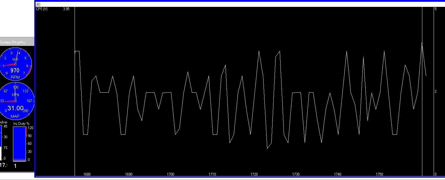
but oddly... when i just crank the engine a lil at a time without it actually "running" i get results more like what i would have expected....
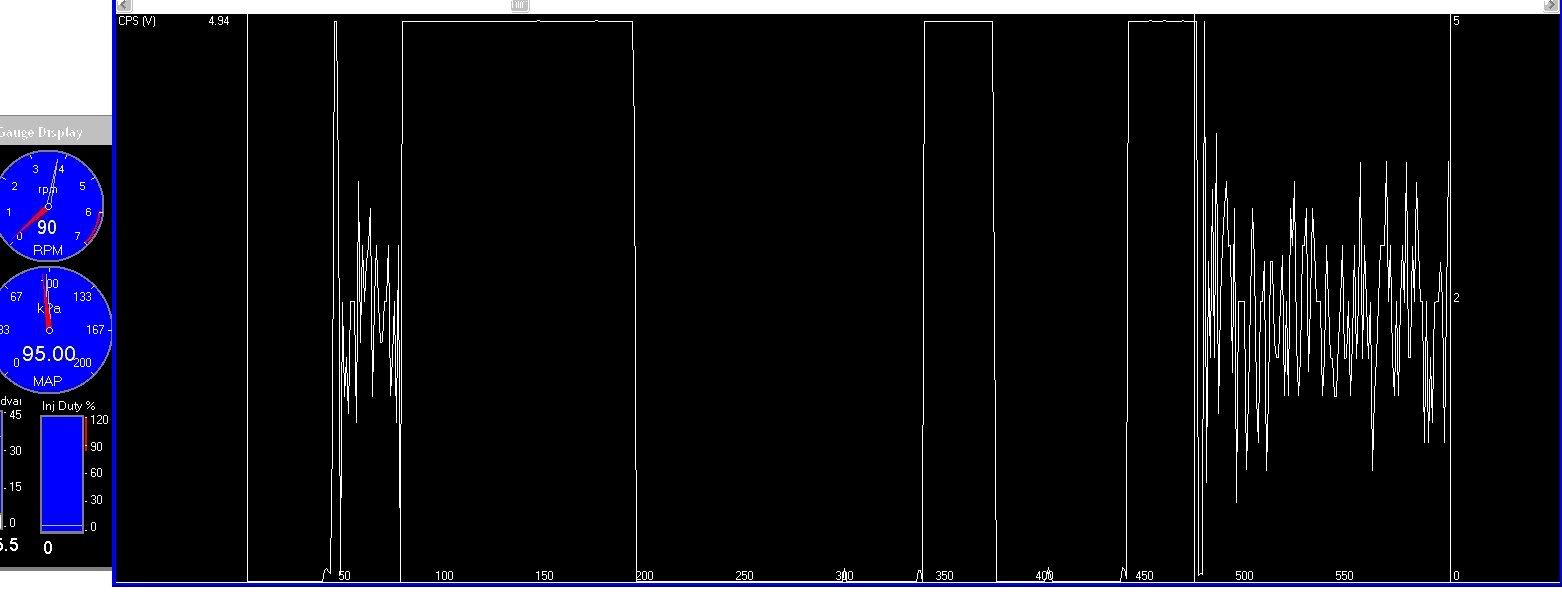
So is HPT just too slow to accurately record the wave? is the engine spinning too fast? and so we are just getting random spots at idle, but in actuality it is more of an on off binary type input?
This just confused me way more than i was before...

^That is exactly what a VR sensor looks like at speed. You might have some losses due to the logging delay but for the most part...thats what your gonna get. You show an good well spaced spike at equal length on and off there, it doesn't dip all the way down at times but the difference is there. This might prove the need for an LM1815 to be run in line before we can do anything with the signal. The LM1815 will fix that up and give you a good signal.
"Never argue with an idiot. They'll drag you down to their level, then beat you with experience!" -Anonymous
now i dont mind putting some time and research into a lil project like this....
But how much money do you think i am going to be looking at in electronincs to convert the CPS to a usable signal?
I can buy their flying magnet sensor for like $70, and then just have to figure out how to safely mount it...
But i dont learn much that way.... And i would imagine the electrical components should be cheaper than $70... but who knows.

An LM1815 is like $8.00 IIRC and simple circuits shouldn't be more than $10.00 after that + maybe $10.00 for a nice enclosure.
"Never argue with an idiot. They'll drag you down to their level, then beat you with experience!" -Anonymous
Interesting subject and one that I explored a few years ago but with a different path of making a sequential firing setup over a waste spark firing setup.
My theory was that if you could just take your ICM outputs which is basically a 1/4 and 2/3 firing sequence and convert that dual pulse to a quad pulse, which would then give you your 1-4-3-2 firing order or whatever order it is that makes the engine work.
So I was thinking of using a binary counter style integrated circuit which could possible use a dual pulse timing and literally convert it into a 4 pulse output.
I researched and asked some college instructors if something like this would be feasible and yes, they said it was but had no clue what sort of timing circuit could do such a change of pulsing.
Eventually I gave up on the research but reading this thread has got me thinking again with what you're trying to do.
So my question would be, why are you trying to come off the cps instead of a signal that is already there with the ICM output?
This we know is a simple 12 volt output (if I remember correctly) and can be used more readily than a hall effect output or even a moving magnet output.
Heck, for that matter, why not devise some kind of way in which an optoisolator could be used to provide your trigger you may be using for the MSD box.
Anyway, I'll be following this thread with interest, even if I didn't make much sense.

Good luck Joshua and Ken.

Barring having to go with a distributor system (which was also on the brain some time ago), this may be a good way to have true sequential firing for individual coils.
Misnblu.com
Newbie member since 1999
Thank you Dave and JBO! 

The ICM will give you a great square-wave signal yeah(tach signal)...but you cant tell which peak is for Cyl 1 or for another Cylinder. I did exactly like you describe up there. I used fast switching NPN transistors. I also used a single flying magnet. In this case, the ICM is 100% useless and it doesn't give you any information as far as where the crank is at. The cam however is directly connected to the crank and therefore the crank position can be known.
"Never argue with an idiot. They'll drag you down to their level, then beat you with experience!" -Anonymous
Ken, the signal you graphed when the engine was running does not look exactly like a VR signal. It looks like a mess! Regardless of the sensor type, be it VR, Hall effect, or "flying magnet," the signal it produces should be consistent, regular, and repeatable. If you look at the signal from the 2nd image, the cranking engine, you'll see there's a lot of noise in the low portion of the wave. It appears in the first image that this noise may have increased after the engine was started. Did your pickup wires run over the ICM or near any solenoids or coils such as an injector? It actually looks like an ignition secondary pattern in the low portion of the cranking engine CMP signal, with a high spike representing the firing voltage and the smaller and possibly decreasing pattern representing the coil "ringing" as energy dissipates. It's very easy to pick up noise in an engine bay and you need to watch how wires are routed. Oh yeah... If HPT is able to display the repeated cycles of noise than it's fast enough to capture the CMP signal which, if the cam sensor is 50%DC per cam rotation, will transition once per crank revolution.
I looked at the MSD 2346 cam sensor kit. It's supplied with a 3/8" diameter magnet which, if mounted as close as 2" to the center of a cam gear, could never provide a 20% DC signal. I think the reply on the MSD forum might be confused, as the DIS-2 literature lists spark duration as 20 deg. Chances are MSD uses the zero threshold as the magnet crosses the sensor rather than a 20% DC "battery amplitude" signal. The magnet generates an A/C signal which increases in amplitude with RPM. It simply doesn't know or care what battery voltage is.
Finally, to say there's no information about crank position from the crank position sensor is not correct. There is relevant information beginning each time the synch notch passes under the OEM CPS sensor. Starting with the synch notch and the elapsed time between it and the next provides a reference for the crank position as well as the amount of time required for a specific degree of rotation. You can always tell when #1 cyl is at TDC because that event always occurs a fixed number of degrees after the synch notch. What you cannot tell is whether #1 is on TDC of the compression stroke or the exhaust, a function determined by the cam.
HTH
-->Slow
^The signal looks exactly like a cheap VR sensor to me. Use an LM1815 and it will work fine. If you actually notice the voltage changes are consistent, honestly thats all you need. I think that is rather useful and have seen and made worse work just fine.
True, I'm not sure why they need a 20degree duration as that struck me odd aswell.
Wrong, when your MSD is looking for a pulse input you can't give it the straight crank sensor signal...that's why I said what I said. You can obviously tell where the crank is at with the crank sensor when you map out the teeth. But if you only running from tooth to tooth(peaks from the sensor output) and driving events everytime...the crank sensor IS useless in knowing where the crank is at. Get it? See why I said that? Rather when you drive off a rising edge from the cam gear, the crank position can be known, but not from the crank position sensor...its useless.
I just ran a magnet for my COP and it worked great, saved alot of hassle, but this isn't impossible.
"Never argue with an idiot. They'll drag you down to their level, then beat you with experience!" -Anonymous
^rising edge of the cam CPS pad rather...not gear. But yes again, if the MSD is going to trigger a timing event every time it sees a rising edge, without mapping out and waiting for a sync which it doesn't...then the crank sensor is useless for knowing where the crank is at...and in this case it is. Rather once you see that same rising edge from the cam, there is only one position that crank can be at. That is how the crank position can be known off the cam but not off the crank.
"Never argue with an idiot. They'll drag you down to their level, then beat you with experience!" -Anonymous
I think you're mixing terms, whether it's in your understanding or just in the way you're describing it I don't know.
COP refers to the physical placement of the coils, not sequential firing of the coils. There is no reason why two COP coils can't be fired in a waste spark method. There's still plenty of spark energy available to deliver good combustion.
I never said to use the crank signal directly (I did suggest trying the cam sensor signal directly) . On the 7 notch system used in the 2.4, the REF pulses delivered by the ICM always begins at the second notch after the synch notch passes the crank sensor. With the first pulse delivered 60 deg BTDC for cylinder #2/3 pair, each subsequent pulse occurs 60 deg BTDC of the next cylinder in the firing order. To ensure the count is correct, the synch is monitored with each crank revolution. If the synch signal fails to be delivered to the ICM within a specific number of pulses, the ICM stops generating REF pulses. So even for a system which only produces a spark on every pulse, this pattern always begins with the first pulse occurring at the same cylinder. From that point you get a pulse every 180 degrees of crank rotation. You cannot synch a sequential ignition from this, but you definitely have crank position information.
If you're used to looking at VR signals which look like the one above, you're not used to looking at OEM quality sensor signals. I've been a tech for almost 20 years and a signal like that would never "fly" in the automotive world. Further, the cam sensor is a Hall effect sensor and the signal scoped above is not correct for a Hall sensor. The correct answer here is not to design a circuit based on that trace, but to scope the sensor again and determine why the trace is not correct for the sensor type.
I *may* have access to a 2.4 engine in the near future. If so, I can try and capture a cam / crank trace on the shop's scope then move it to a pc and upload it here.
-->Slow
slowolej wrote:I think you're mixing terms, whether it's in your understanding or just in the way you're describing it I don't know.
COP refers to the physical placement of the coils, not sequential firing of the coils. There is no reason why two COP coils can't be fired in a waste spark method. There's still plenty of spark energy available to deliver good combustion.
Look, you can't come in here and read two posts and start correcting people...you need to read. This whole thread is about making a COP(Coil on plug) setup using the cam position sensor. Yes, you can run COP-DIS but in every circumstance where you have 2 coils with wires running to the second plug they have been named COP-DIS(Typical of budget Toyota systems). The only system named "COP" is a true single independent coil to a single independent plug. All others are NOT true COP. The advantage whether some think its worth it or not would be longer coil dwell times and the ability to have a cleaner setup. I Know there is plenty of power available in the DIS setup, but a better coil on a CDI ignition is possible with awesome dwell with a COP setup. Not to mention higher rev capabilities since dwell times comes into play when you want to run hot coils on a DIS system. Good luck running high boost with DIS or COP-DIS over 7k RPM even with a CDI....gooooood luck.
slowolej wrote:
I never said to use the crank signal directly (I did suggest trying the cam sensor signal directly) . On the 7 notch system used in the 2.4, the REF pulses delivered by the ICM always begins at the second notch after the synch notch passes the crank sensor. With the first pulse delivered 60 deg BTDC for cylinder #2/3 pair, each subsequent pulse occurs 60 deg BTDC of the next cylinder in the firing order. To ensure the count is correct, the synch is monitored with each crank revolution. If the synch signal fails to be delivered to the ICM within a specific number of pulses, the ICM stops generating REF pulses. So even for a system which only produces a spark on every pulse, this pattern always begins with the first pulse occurring at the same cylinder. From that point you get a pulse every 180 degrees of crank rotation. You cannot synch a sequential ignition from this, but you definitely have crank position information.
I never said getting the crank position isn't possible from the crank position sensor. I also know what the ICM does with the crank signal input and what it can give you, but in this case I feel it would be easier to just use the CPS...depending on when the rising and falling edge fall with crank position. See with the CPS if it is in a copacetic/perfect position would be much easier since it would be solid state and not a momentary. You would need a setup like the one I built which is more difficult than two transistors which is what I'm shooting for. If you build a simple transistor bridge to use a solid state input to make two wires into 4 outputs and use only the rising and falling edge(to activate and de-activate the transistors) of the cam CPS then you CAN make the dis triggers into COP triggers. That is what this whole thread is about. I and others here don't need a lesson on what or how the crank sensor reads. So when the cam sensor is on a falling edge or flat low voltage you have the two triggers sent to cyl 1&3, then when the CPS is reading a rising edge or flat high voltage you switch the two wires to the other set of opposing coils. Basically removing one spark plug from the DIS coils and have the coil only fire one plug for each coil trigger...get it? Maybe using the REF could be a possibility but I'd first rather try the CPS. Honestly they both could get the job done, and interesting info since I guess thinking about it...I probably could have made my setup using that REF reading and not have to run the flying magnet setup. Hindsight is 20/20, I honestly didn't even think about it.
slowolej wrote:
If you're used to looking at VR signals which look like the one above, you're not used to looking at OEM quality sensor signals. I've been a tech for almost 20 years and a signal like that would never "fly" in the automotive world. Further, the cam sensor is a Hall effect sensor and the signal scoped above is not correct for a Hall sensor. The correct answer here is not to design a circuit based on that trace, but to scope the sensor again and determine why the trace is not correct for the sensor type.
You are right, this isn't a output for a typical hall since that would be a flat square peaks but I have seen halls that have internal inductance read like that. So, it could be possible.....and according to the title of this thread I do not yet know exactly what the CPS reads and when..so. As far as usefulness....if that is the best that sensor can do, it still can be used. I'm not sure if in your 20 years of experience you have used an LM1815 but they work wonders and completely filter the input of some of the nastiest raw sensor signals and straighten them out....I have about 2 years experience and have used them several times and every time it works great, and yes I have seen worse and made it work just fine.
slowolej wrote:
I *may* have access to a 2.4 engine in the near future. If so, I can try and capture a cam / crank trace on the shop's scope then move it to a pc and upload it here.
Cool, that would be very helpful.
Sorry to get all ugly, but it doesn't seem your informed on the back story here. I'm trying to let the stock ECU handle when to fire the coils and just using a simple transistor setup to switch two triggers into 4 triggers and using a know point(CPS) to tell the bridge when to switch the two inputs to the other two outputs...get it?
Anyway, I know the circuits I'm running works...I'm running it now. I'm just thinking about trying to get it to work with the CPS straight. Which at this point I'm not ready to try to F with the CPS since I'm using a flying magnet hall and it works great.
Please don't take this out of color, I did mis-read your post as far using the crank or cam, so I'm sorry. If the CPS turns out to not help(edges drop in the wrong spots) then the ICM will be the next best and thanks for the enlightenment. I'm just trying to do an easier setup using on-off circuit design. If the ICM was to be used I'd have to rig up something that would act like a electronic distributor...possible but honestly possibly beyond my level of expertise. I'm up for the challenge if it comes to that, but I always try to go simple first. In either case I still need to figure out how to wire-up a fail safe that switches to COP-DIS in the event of sensor failure(or REF drop-out) which right now I'm not running. All I have now is a set of jumpers and I have to jump to disable in the event of dropout. I need to figure out a way to make this electronic as this right now is in the physical and requires a hood pop.
Any thoughts would be helpful...I thought about a RC circuit that would full saturate after a worst case scenario(2X the time required for next pulse even if at idle) then when that circuit grounds(full sat.) it would kick out and around the entire deal. But I don't like that idea. Eh.....
"Never argue with an idiot. They'll drag you down to their level, then beat you with experience!" -Anonymous

Joshua, any way that you can reveal your wiring hookups to the above LM1815? (thanks to National Semiconductor for the pic)
This has my interest up in reading this.
I'm not sure if you are trying to keep this secret or just trying to work this out to actually work but again, the concept has me interested and would love to see your work.
You can PM me the info or even email if you so desire.
Sorry to be a nuisance about the information but like you, this has been my interest for several year in getting a waste spark system to run a sequential spark system for the car.
Misnblu.com
Newbie member since 1999
Thank you Dave and JBO! 

"Big Picture" scan. Cam pulse is yellow, crank pulses are green.
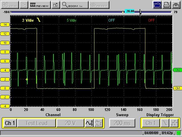
This is 50 deg crank rotation. Notice DeltaT in box in RH corner.
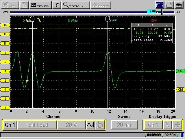
Time from crank pulse begin to cam pulse transition from 10V to 0V.
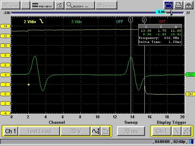
Time from crank pulse begin to cam pulse transition from 0V to 10V.
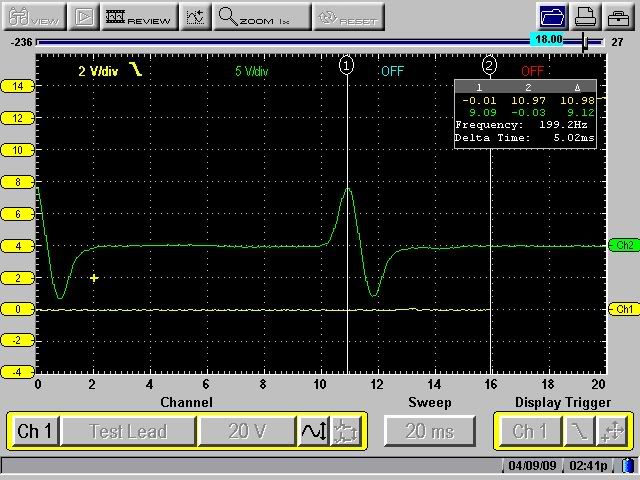
With the time for a fixed amount of rotation known you can work out the number of degrees between a crank pulse and the cam pulse transition. With the large picture you can work out where cam pulses occur in relation to the synch pulse.
Ken's scans seemed to have too many pulses for 1000 rpm compared to crank rpm. If so, even good filtering wouldn't know which pulses were valid. Hence the suggestion to re-scan. You seem to want to build stuff right, that's the only reason I mentioned it.
I didn't know the back story, only what was posted in this thread. I wanted many, many moons ago to work out a circuit to use (2) 4 cyl DIS ignition ignition systems on a V8. I needed to determine how to synch the two modules to the single EST signal from the ECM. Two crank sensors at 90 crank degrees would give me correct alternating firing from the modules when not under ecm control, and tying the REF outputs together would create a correct V8 REF signal for the ecm, but there was no guarantee the EST output would ever be synchronized to the correct module without a generated REF signal. Couldn't get any help designing the circuit so I ended up enrolling in school as EE and CS major. Nice little detour, never did build the circuit.
4 cyl DIS has huge amount of time for dwell imo. CDI multiplied through primary/secondary windings makes big sparks able to leap .100" gap with no trouble. Problem with OEM coils at very high voltage and very high resistance in the cylinder gets to be insulation breakdown. Introduce new path to ground and secondary voltage hauls ass to get away from plugs. Otherwise, 80-100kV is enough to fire plugs. Always wanted to use 4 MSD ignitions with individual coils to beat the 3k rpm limit for multi-spark. Each ignition would see 1/4 time between firing events, should allow multi spark to at least 10k rpm. PCM splitting REF to two pair of coils and a version of your circuit splitting that pair again could allow this.
HTH
-->Slow
Forum Post / Reply
You must log in before you can post or reply to messages.


